Electronic mirror adjustment:
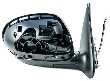
In the mirror housing of a car with electrically operated exterior mirrors, two electric motors are mounted. One electric motor moves the mirror glass up or down. This is the vertical movement. The other electric motor is for the horizontal movement; left and right.
To control the exterior mirrors, a button is integrated into the car’s interior. This can be in the dashboard, the center console, or the door.
The signals from the switch reach the control unit (the ECU). This is usually the comfort control module or the door control module. These control modules are often connected to the CAN bus. When the control unit receives a signal from the switch, this switch (in older vehicles) or the ECU (in newer vehicles) will activate the electric motors through an H-bridge to move the mirror glass.

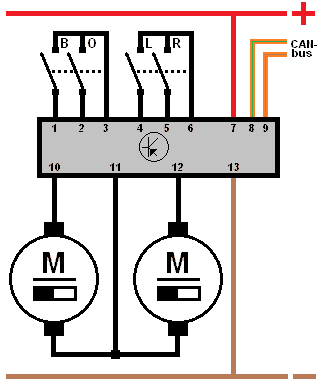
In the wiring diagram, it can be seen that the power supply and ground are connected to pin 7 and pin 11. The CAN high and CAN low are connected to pin 8 and 9 with the ECU.
The switches for the vertical movements are connected to pin 1 and 2. Pin 3 is the power supply for these two switches. The same applies to pin 6, which is the power supply for the switches for the horizontal movements on pin 4 and 5 of the ECU.
The electric motors are connected to pins 8 and 10. The left motor (pin 8) is for the vertical movements. The right motor (pin 10) is for the horizontal movements. On pin 9 is a wire connected to both motors. Depending on the situation, the ECU can switch either a positive or ground here. How this works is described in the following paragraphs.
Vertical adjustment:
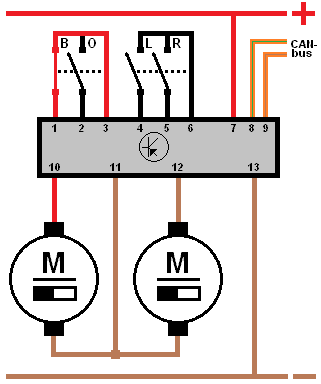
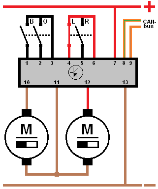
This explanation refers to the two images below.
When adjusting the mirror glass upwards, the left motor is controlled by switch B on pin 1. The control unit then switches a power supply to pin 8, which is connected to the motor with a wire. Ground is switched to pin 9. The left motor will rotate until switch B is interrupted again.
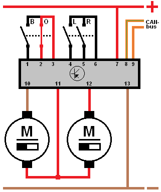
When adjusting downwards, switch O will close. On pin 9 of the control unit, the power supply is now applied, and pin 8 becomes ground. Since the positive and ground on the motor are reversed, the motor will rotate in the opposite direction (downwards instead of upwards). This is shown in the images below.
When the motor for vertical adjustment rotates, the motor for horizontal adjustment must remain stationary. Both connections of the motor that must remain stationary are shorted to ground or positive on pin 9. On pins 8, 9, and 10, a power supply or ground can be switched independently.
Reversing the polarity of the motor to change the rotation direction is possible with a so-called H-bridge. This circuit of four transistors or FETs is built into the ECU. The ECU controls the appropriate transistors in pairs (one for positive and one for ground) to determine the current direction to the motor.
Horizontal adjustment:
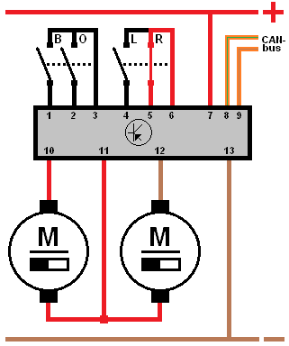
This explanation refers to the two images below.
When adjusting to the left, switch L will close. The right motor receives power via pin 10 on the control unit. Ground goes through pin 9.
Since the left motor (for vertical adjustment) must not rotate now, it is also grounded on pin 8. The left motor is thus shorted to ground. The right motor rotates at a constant speed until switch L is no longer operated.
When adjusting to the right, the power and ground on the right motor are reversed again. The motor will now rotate in the opposite direction.
Now, on pin 8 of the left motor, not ground but power is applied. Otherwise, it would also start rotating. Since both sides are switched to positive, the motor remains stationary.
Mirror adjustment with memory function:
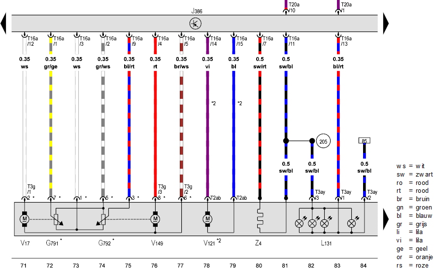
Modern vehicles have a mirror adjustment with a memory function. The ECU controls the actuators until they reach the desired position. Position recognition is done using potentiometers. More information can be found on the page about the potentiometer.
In the diagram, we see the potentiometers G791 and G792. The potentiometers receive a 5-volt power supply and ground from the ECU. The signals are sent to pin 1 and 9 of connector T16a.
The ECU recognizes the position of the actuators V17 and V149 by reading the signal voltages of the potentiometers. For a preset value in memory, the ECU keeps controlling the actuators V17 and V149 until the signal voltage equals the stored value in memory. Example:
- The car is unlocked with key A;
- The stored value of V17 is 3.6 volts;
- The measured value of V17 is 2.9 volts;
- The ECU controls motor V17 until the potentiometer gives a signal voltage of 3.6 volts;
- When the car is unlocked with key B, with a stored value of 2.9 volts, the same process occurs to reach the stored value.
The operation, versions, and possible malfunctions are covered on the page Potentiometer.
Related page: